 San Antonio Area Hams
Removing Alternator Whine
I recently installed a new transceiver in my truck. On the first day of using the new radio I got reports that I was transmitting very noticeable alternator whine. I could also hear it on receive and when the radio was quiet. I checked the diodes in the alternator, verified I had good grounds, and I even ran the truck with the alternator removed to be sure that the whine was indeed from the alternator.
The alternator produces AC, which is rectified into DC. The problem is the rectification is not perfect. The DC output will have a small AC signal riding on it. That AC signal will have 9 cycles for each revolution of the alternator. Suppose your engine is idling at 600 RPM and the drive pulley ratio to your alternator is 1:3. At that engine speed your alternator is turning 1800 RPM, which is 30 rotations per second. Each rotation gives you 9 cycles of AC. Do the math and you get a 270 Hz sinusoid (not a perfect sinusoid but close enough). Cruise down the road at 2000 RPM and you get a 900 Hz sinusoid riding on your DC power supply.
I tried an off the shelf filter from Advance Auto. It did very little so I decided to build a filter. The first filter I built worked VERY well. The problem is that not everyone has the tools required to build that filter so I decided to figure out a filter design that could be built in less than an hour by anyone with basic tools, have a cost under $20, and handle a current of at least 20 Amps.
Parts List: |
Est. Cost |
1/2" Quick Link from Lowe's |
$2.98 |
6x3x2" project box from Radio Shack |
$3.79 |
20' roll 12 gauge red hook up wire from Radio Shack |
$4.99 |
4700 uF 35V capacitor from Radio Shack |
$5.29 |
18" of black 16 gauge wire |
|
electrical tape |
|
GOOP or similar glue |
|
3 zip ties |
|
Total: |
$17.05 |
Directions below
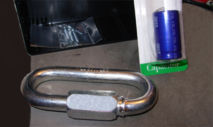
1/2" Quick Link will be used as the inductor core. A fellow ham, Dave KC1LT, suggested using a shackle. I went to get a shackle and came across this quick link. I went with the quick link to make more efficient use of project box space.
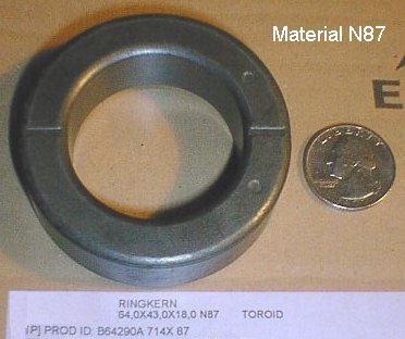 Webmaster note: I found out from local ham W2IK about a source of inexpensive ferrite toroids on eBay from "surplusmaster" userID. He frequently sells batches of ten (10) 64mm (OD) Ferrite Toroids which work better than the shackle shown above. I've confirmed this performance level with the author of this article. Depending upon when someone asks me, I might have a few extras available to share for such projects.
If you use this instead of the oblong shaped shackle as the core to wrap, you might need to adjust the size of the plastic project box to accomodate the wrapped width of the core.
I'll be building one or more of these in the near future, but that will leave me with a few spares, even after building some HF RF Choke Coils using this toroid.
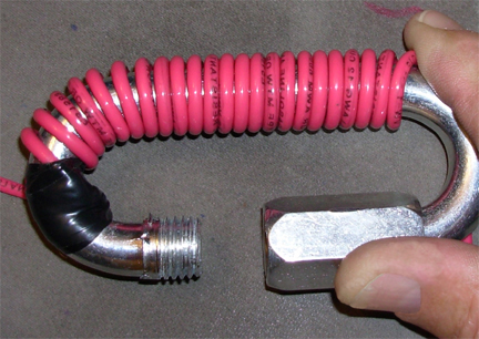
Beginning the winding
Wrap the hook up wire around the closed side of the quick link starting from the left as shown. Leave about 9" of wire free on the left end. Try to keep the winds as close together and tight as possible. On the last layer space the winds so that you have 9" of wire left on the right end. Use all 20' of wire.
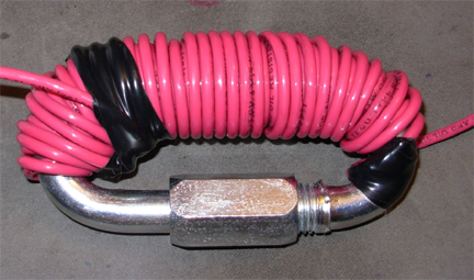
Above is the finished wrap
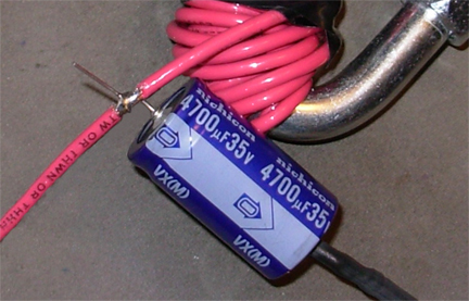
Wrap the coils in electrical tape and close the quick link. About 1.5" from the right end of the inductor strip 1/4" of insulation off the red wire and solder in the + lead of the capacitor. Make sure you observe the capacitor polarity. In the picture you can see the negative arrow on the capacitor pointing down. Solder the 18" piece of black wire to the negative lead of the capacitor. (Above)
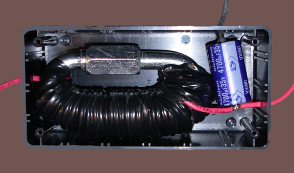
Cover the solder connections and capacitor leads with electrical tape. Drill a 3/16" hole in both ends of the project box for the red wires. Drill an 1/8" hole in one end of the project box for the black wire. Run the wires through the holes. Put a zip tie on each of the three wires to limit how far the wires can be pulled out of the box. Make sure to leave a little slack in the wires inside the box. Using GOOP or some other thick strong adhesive, glue the capacitor and inductor into the project box. Leave the cover off until the glue dries.
+12V Side with the capacitor to radio
Black Ground +12V to battery
Measured Filter Response:
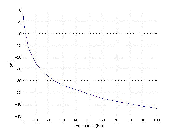
I made this measurement using a low frequency signal generator and an oscilloscope. At 25 Hz the filter has better than 30 dB of attenuation. In other words for frequencies above 25 Hz the noise power has been knocked down by more than a factor of 1000.
I am new to practical electronics. By answering basic questions and making suggestions several folks contributed to this. In particular Dave KC1LT was very helpful. I hope this information is useful. If you use this design to build a filter or if the information presented was useful please send an email to kb1mvx@comcast.net and let me know it was worth the effort to put this together.
73 de
Jim
KB1MVX